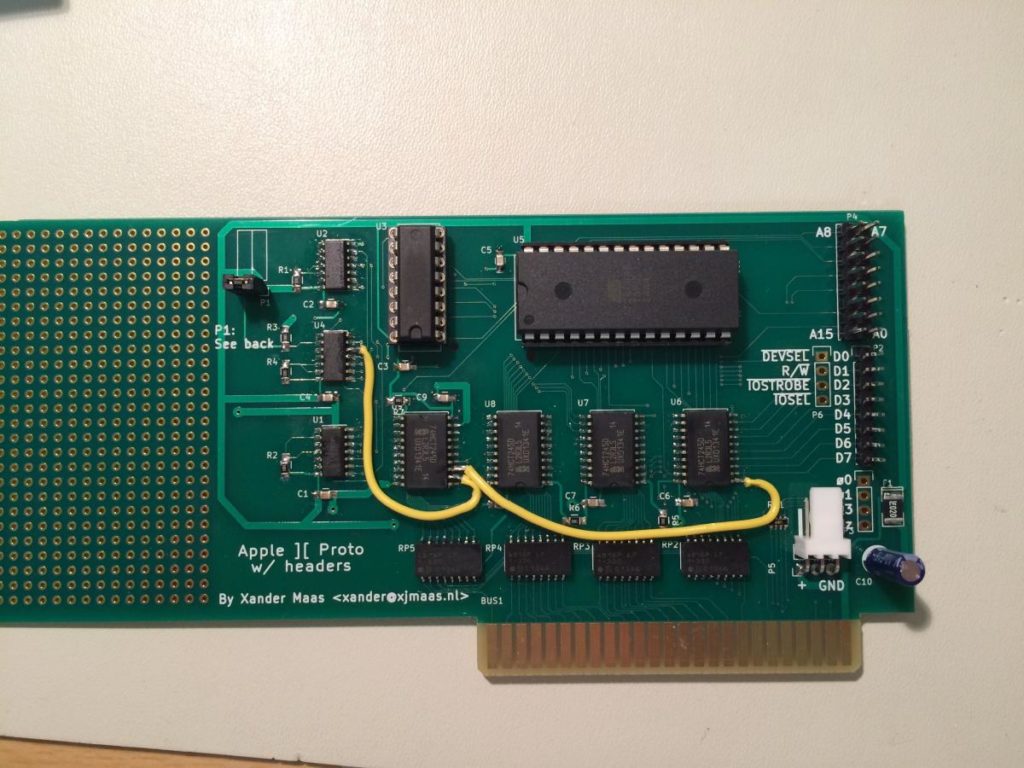
I did receive the PCBs for the Proto card (to work with EEPROMs).
First thing I noticed, is that I made some small errors with the Rev C design. This meant I had to cut some (two) traces and lay some wires.
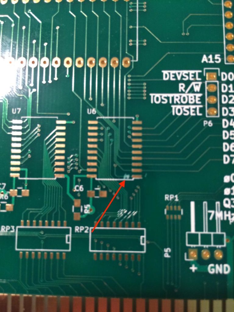
Cut trace #1
I had to cut a trace at pin #1 of U6 (a 74HCT245, the A-B signal). I had it hardwired together with the Write Enable jumper header, which means that we can only send data to the card when the jumper is installed. This is not my intention, as I also want to be able to send data in 'Normal Operation mode'
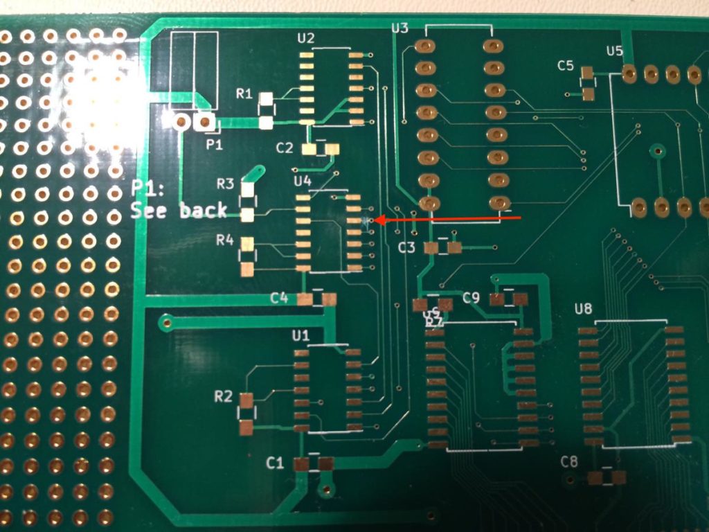
Cut trace #2
The next trace to cut is at U4, pin #5. This was 'just' a drawing error, on my breadboard I did wire it all right....
Result
What results is a board with two wires to correct my errors.